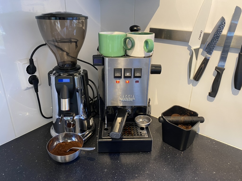
I’ve been using the GAGGIA Classic Pro for about a year now and not only have I really enjoyed using it, but also maintaining it. The simplicity of the machine encourages you to take it apart and have a look around inside. The simplicity also comes with the fact that there are no advanced features, the machine is really quite manual. This, what some might call a downside, was for me actually one of the reasons to buy it. I wanted a semi-automatic process, because I wanted to be able to enjoy the ‘ritual’ of brewing a cup of coffee.
However the not automated part (me), is not as reliable and exact as a machine. And where I encountered this first, was when counting the seconds my espresso shot was brewing for. If I counted at all, because most of the time I did forget to count and had no way of telling whether my espresso was actually a shot or a lungo. So I decided to fix this problem and make my first modification to the machine.
After some Googling I quickly found solutions to this problem online, ones that I could purchase and install myself. They were timers that started running the moment you pressed the brewing switch. However they were quite expensive, and this project sounded like something I could handle myself and learn a thing or two. So I opted to do it myself. In the end I probably spent more time and money prototyping than when I would’ve bought a solution, but what’s the fun in that?! And (spoiler alert) I even learned how to make my own pcb in this project!
The design
I knew I wanted a small screen that counts the seconds since I hit the brew switch. When I had a look around for existing solutions I also came across a device prototype that tackled the same issue on Github by @steinbeck. This inspired me to take similiar approach. I had some experience with programming Arduino’s so thats what I used as the brains, to convert the 230AC to 5DC I used the HLK-10M05 and to display the numbers I wanted to use a simple SSD1315 Oled screen. Now I had to figure out a way to connect it all together.
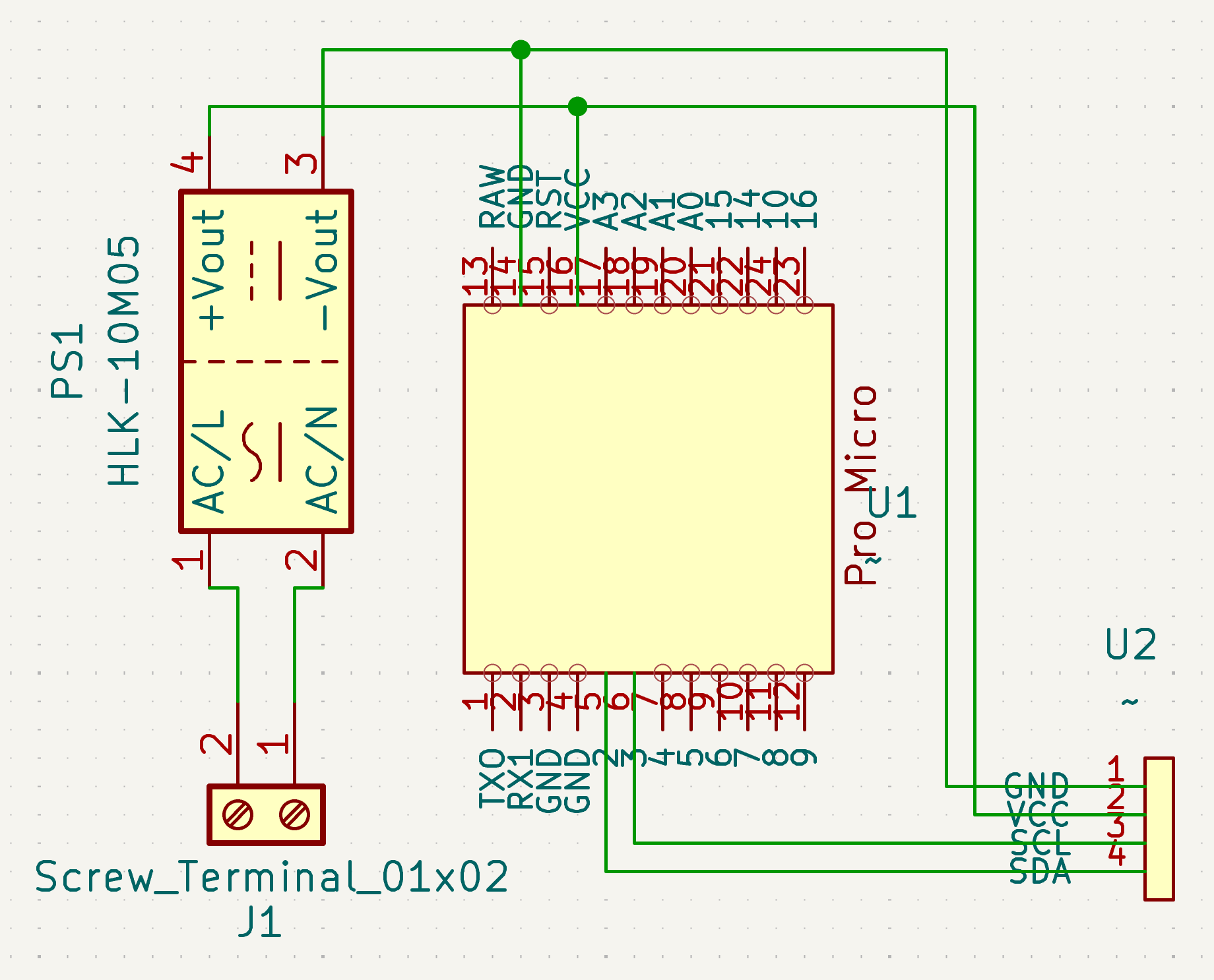
The circuit itself was quite simple. Starting with the wires from the brew switch, these connect to the screw terminals that corresponds with the AC pins on the HLK converter, which converts the 230v to 5v that powers the Arduino Pro Micro. Then there are only 4 wires that go from the Arduino to the OLED screen. For convenience sake, I put a JST connector with a ribbon cable in between so that I could easily disconnect the screen if necessary.
I tried getting this to work on a prototyping PCB, even though the circuit was quite simple I quickly got annoyed with my low quality soldering tin and did not continue that route any further. The simplicity of the circuit gave me the confidence of skipping the prototyping fase altogether, what could go wrong!? I wanted to design a PCB for this project. I’ve watched many YouTube videos of doing this exact thing with PCBWay, a service that makes and ships from custom PCBs from China. I needed to make sure the design was good or I had to order new PCB’s and wait another couple weeks. So I consulted the only source I had when it came to pcb design… Claude! It confirmed that what I whipped up to be good.
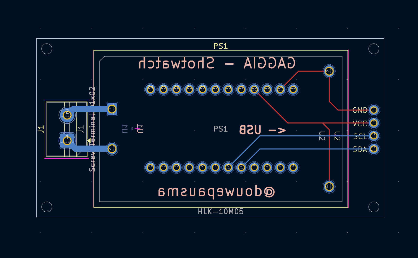
I did the designing of the PCB in KiCad. KiCad has a very useful PCBway plugin, I used that to make the order and after one or two weeks I had the PCBs in the mail! In addition to the PCB I ordered all the required parts from AliExpress. You might be able to make up the name I gave this project 👀, Shotwatch!
‘Shotwatch’ is a combination of the words ‘Espresso Shot’ and ‘Stopwatch’
Programming the controller
The only thing this controller needs to do is count up the seconds since it has been turned on and display it on the screen. The code below exactly does that, it’s quite simple really. Create a loop that updates the screen every second and display the loop iteration.
#include <Wire.h>
#include <Adafruit_GFX.h>
#include <Adafruit_SSD1306.h>

#define SCREEN_WIDTH 128 // OLED display width, in pixels
#define SCREEN_HEIGHT 64 // OLED display height, in pixels
#define OLED_RESET -1
Adafruit_SSD1306 display(SCREEN_WIDTH, SCREEN_HEIGHT, &Wire, OLED_RESET);

int counter = 1; // Offset the counter here to make up for the startup delay.

void setup() {
  Serial.begin(9600);

  // Initialize OLED
  if (!display.begin(SSD1306_SWITCHCAPVCC, 0x3C)) {
    Serial.println(F("SSD1306 allocation failed"));
    for (;;); // Don't proceed, loop forever
  }

  display.clearDisplay();               // Clear display buffer
  display.setRotation(2);                 // Rotate the display (it's mounted upside down)
  display.setTextSize(9);                 // Text size
  display.setTextColor(SSD1306_WHITE);     // Text color
  display.setCursor(16, 0);             // Position the cursor
  display.display();                    // Show initial empty display
  delay(1000);                             // Brief message
}

void loop() {
  display.clearDisplay();
  display.setTextSize(9);
  display.setTextColor(SSD1306_WHITE);
  display.setCursor(16, 0);
  if(counter < 10) display.print(0);   // Add Leading zero below 10
  display.print(counter);              // Print counter
  display.display();                   // Show on screen

  counter++;                           // Increment the counter
  delay(1000);                         // Wait 1 second
}
Assembly
I soldered everything together and flashed the controller, to test it I just used a standard power cable that I stripped and attached to the screw terminals. And it worked on the first try! Well almost, the numbers were displayed upside down. But that was an easy fix, I rotated the display 180 degrees in the code and reflashed the controller.
The assembly is not complete, there’s only one thing left to do and that is to design and print a housing for it. I have a lot more experience with this part. It still took me a couple tries, but as usual they were all measuring errors. The case consists of three parts, a case and lid for the Shotwatch itself and a part to hold the screen on the side of the GAGGIA. I’ve embedded some magnets in the Showtwatch case, so that it will stick to the inside of GAGGIA. There are also some threaded inserts in the body of the Shotwatch case so that the lid is able to be fixed on with screws.
Shotwatch screen case design
Shotwatch case 1/2 design
Shotwatch case 2/2 design
Installation
Finally all that was left to do was wire the Shotwatch behind the brewing switch. I didn’t want to cut any wires so I used some piggyback connectors to connect both the Shotwatch and the brewing circuit behind the same switch (you can see this at around 00:25 in the second video below). These wires are then attached to the screw terminal on the Shotwatch. The videos below give a better image of how the Shotwatch was installed.
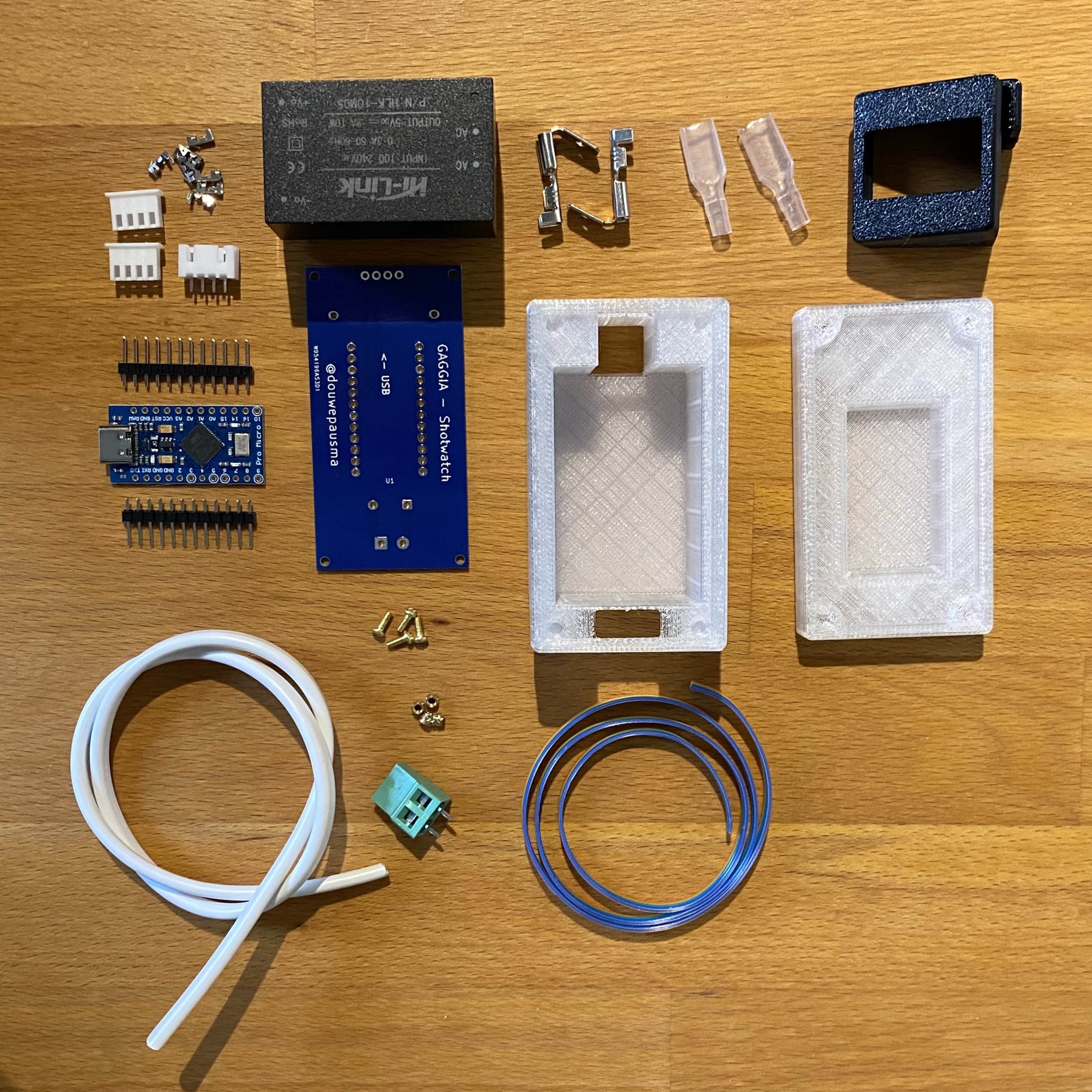
Bill of materials
In addition to the 3 printed parts and the Shotwatch PCB, the following parts are required. You can find all the parts below on AliExpress. Concerning the Shotwatch PCB, you can get this manufactured at PCBWay with the gerber files. And you can print the STL files for the case yourself, or find a place where you can get them printed.
| Part | Amount |
|---|---|
| HLK-10M05(10W 5V) | 1x |
| Arduino Pro Micro | 1x |
| Header pins 2x12 | 2x |
| SSD1315 Oled screen | 1x |
| 4pin JST female connector | 1x |
| 4pin JST male connector | 2x |
| KF128 5.08MM pitch, 2 port screw terminal | 1x |
| 30cm 4 wire ribbon cable | 1x |
| 30cm 18 AWG cable | 2x |
| Piggyback connecter (with insulation) | 2x |
Conclusion
This project was really fun. There was definitely a moment where I wanted to give up, but I am glad that I finished this project even though I almost broke my GAGGIA in the process. About that, I completely left that part out, but I short-circuited the control board while figuring out which pins of the brewing switch I needed to connect the Shotwatch to. Luckily nothing critical broke and I only had to solder on a new fuse, which saved me from buying a new expensive control board. I am so happy that I learned how to design a PCB, and definitely want to reuse this skill in future projects. When ordering the PCB I ordered a couple extra, and gave a ready to install kit to my brother-in-law. It was fun to install it with him and to see this can be done without making any modification to the machine itself.